
Timber frame
Timber-frame
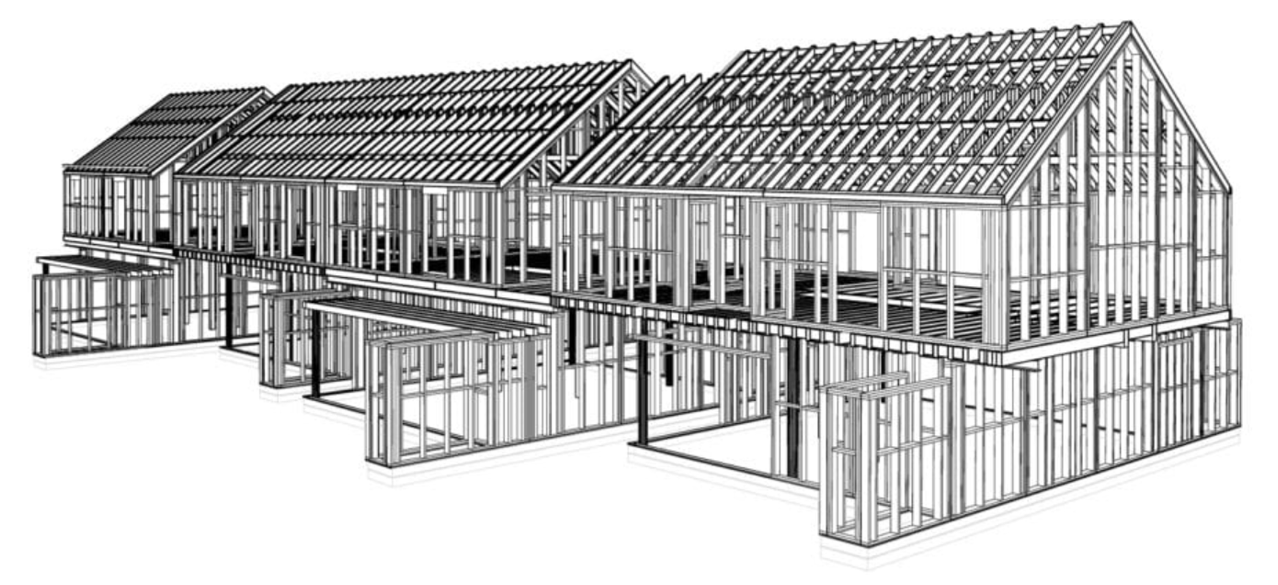
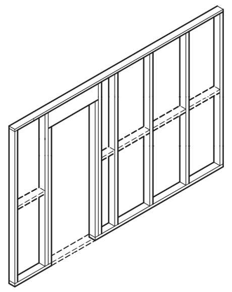
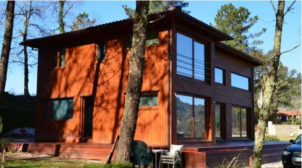
The timber frame (Figure 1) originated in North America during the 19th century as a consequence of two factors: the availability of standard industrial products (sawn wood) and the need to boost a fast construction system, due to the rapidly growing colonisation of the Wild West of the United States. From then onwards, the standardisation and certification of items facilitated modularity and prefabrication, in addition to compliance with quality requirements. Furthermore, the items require a low mechanisation level, which implies low manufacturing costs.
Figure 1: Timber-frame (Rusticasa, 2022)
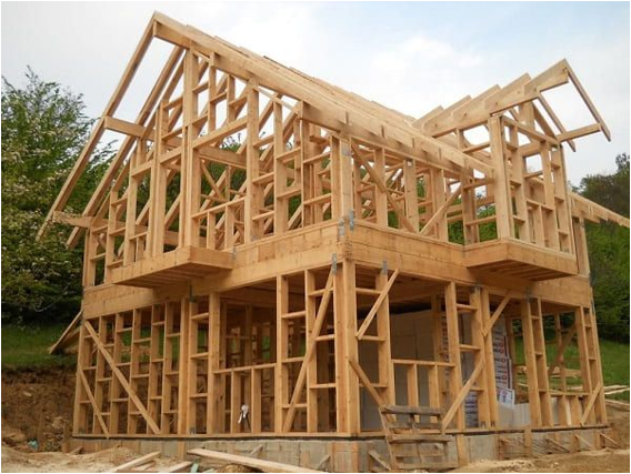
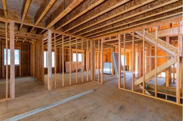
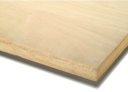
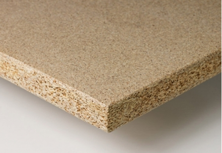
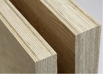
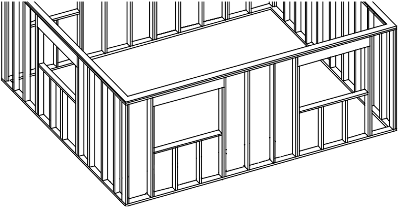
The timber frame structure is composed of a skeleton of uprights and crosspieces (Figure 2), braced with slender structural boards of wood derivatives, such as oriented strand board, plywood, particle board and even laminated veneer lumber (Figure 3).
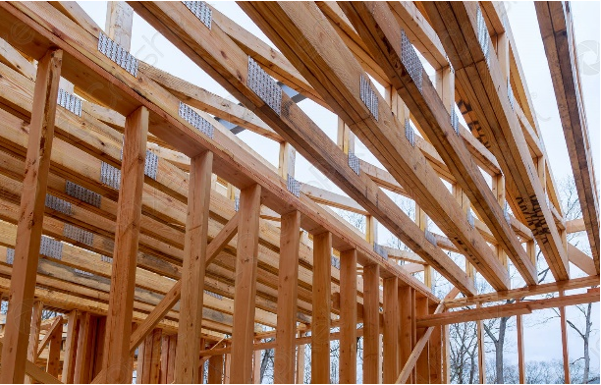
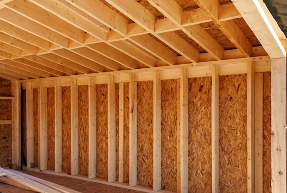

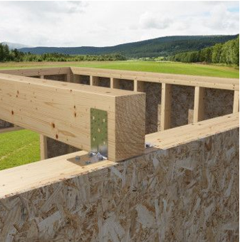
The combination of light load-bearing members, together with enclosure elements, ensure that the set has the necessary resistance and rigidity to overcome vertical and horizontal stress. A large number of members are used, thus distributing the housing load over many small-sized members. For this reason, a major quantity of special construction details is required, although the joints are simple and do not need special interlocks, with iron fittings being sufficient (Figure 4).

The external walls, whether façades or partitions between different buildings, perform a structural and protective function, being responsible for the transmission of stress vertical and lateral to the foundation and, of course, for enclosure to ensure ideal conditions of air temperature and humidity relative to the outdoor environment. The reduced thickness of its walls optimises the housing space (approximately 8% more than bricks), in addition to increasing the comfort of its occupants, thanks to the insulation materials that regulate the humidity indoors, with low thermal inertia and absence of thermal bridges (close to 30% of heat losses in conventional construction). Moreover, a timber frame has a high degree of flexibility, both for the initial design and for changes of the interior space during its use.
Suitable for any type of terrain, a timber frame structure is up to 7 times lighter than a reinforced concrete construction and 17 times lighter than steel, requiring much less substantial and less costly foundations, ideal for terrain with low load-bearing capacity or in poorly stabilised soils (Peraza, 1995). A timber frame structure is usually mounted on concrete slab, on the ground or over an air gap, enabling the construction to rise 20 cm above ground level, depending on the intended use of the building, foundation soil compaction level, thermal requirements and technical feasibility. A physical barrier, sealing strip or other, prevents the damp from rising in the walls through capillarity.
The timber frame is normally made of the wood species most suited to the project’s requirements, reflected in economy of material. Strict control of its water content is imperative so as to prevent significant dimensional variations; its moisture content should not exceed 15%, and dry parts should not be mixed with wet parts to ensure that there are no movements of the structure due to drying.
The uprights (Figure 5), responsible for supporting the vertical load imposed against the wall also contribute to resilience against lateral loads (cutting plane) and provide structure for placement of the wall enclosure and cladding boards. These members usually have a section whose base varies between 30 mm and 45 mm, and height (wall thickness) between 120 mm and 170 mm. However, due to the recent search for energy efficiency, it is common to increase the height of the uprights to 200 mm or 220 mm, so as to increase the thickness of the incorporated insulation layer. For larger sections, the use of structural timber is unlikely; hence, wood derivatives are considered such as glue laminated timber or laminated veneer lumber. In these cases, alternative systems with composite uprights, formed by the combination of smaller-sized structural timber membranes, may be more economic. These uprights are usually arranged at a distance of 400 to 600 mm from one another, depending on the required load-bearing capacity of the wall and the geometry of the interior and exterior enclosure members (boards).
Figure 5: Timber frame structure where the vertical members are the uprights (TRADA, 2008)
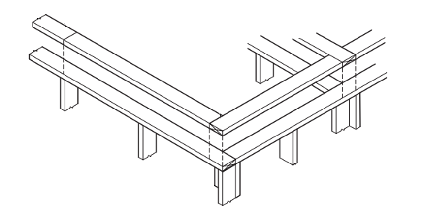
The lower and upper flanges (Figure 6), joining the wall structure and providing the necessary fittings for the enclosure and cladding boards, generally have the same section as the uprights.
Figure 6: Flanges of the timber frame structure (TRADA, 2008)
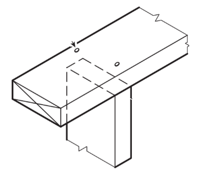
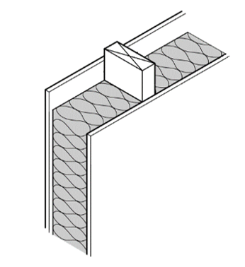
Apart from flanges, the external wall structures may have another horizontal element: interlocking elements (Figure 7). These elements, normally of the same section as the uprights and flanges, despite the inconvenience of interrupting the continuity of any layers for thermal and acoustic insulation inside the wall cavity, giving rise to thermal bridges and increasing the time required for applying insulation around them, limits the lateral deformations of the uprights when under heavy loads and can offer support to the internal walls in “T” type joinery with the external walls. Moreover, they can also work as points for fastening accessories, such as plugs, when placed at some distance from the uprights and wall enclosure and cladding boards.
Figure 7: Interlocking elements of the timber frame structure (TRADA, 2008)
The wall enclosure is responsible for providing the necessary rigidity to support lateral load-bearing, in particular, rigidity of the cutting plane. In terms of protection, the external enclosure especially contributes to the sealing against the penetration of air in the structure and acts in the secondary protection against humidity if the external claddings are applied in lagged timings. Furthermore, both provide a solid base for the fastening of membranes and accessories, such as cable trays and plugs, cover and support the insulation material, and reduce the risk of damage or distortion of the panels before their fastening, primarily during stages that require their handling, such as transport and installation. Notwithstanding this, the walls, in the form of prefabricated panels, often leave the factory only with the external enclosure installed, thus keeping the interior of the panels accessible on-site for services such as passing through and fastening conduits and pipes, and tightening connectors.
The purpose of the breathable membrane is to protect the building from the weather, primarily when the external cladding is applied after the installation of the panels on-site, and offers a second protective layer against rain that might penetrate into the external cladding during the building’s useful life. It also contributes to air tight sealing and, consequently, to reduce heat loss through uncontrolled ventilation.
Normally in timber structure walls, or timber frame, the maximum thickness of the insulation layer is controlled by the dimensions of the uprights (Figure 8a). When wanting to increase the insulation beyond that dimension, the height of the transversal section of the uprights is increased or extra layers are placed, both inside and outside. One such solution is the use of interior service layers (a cladding layer distanced from the enclosure layer of the wall structure) (Figure 8b) which, in addition to its original purpose of sheltering the building’s systems (electric wiring and pipes), can be filled with insulation material. This increases the set’s insulation level by creating a continuous insulation layer, thus precluding any thermal bridges caused by interruptions in the insulation layer of the wall cavity due to the uprights and interlocking elements. Although the insulation is incorporated for purposes of thermal comfort, primarily to reduce heat loss, when made of absorbent materials, it contributes to insulation against air traffic sounds and to the fire-resistance of the external layers.

The anti-vapour barrier is fastened between the surface of the internal enclosure and the heated side of the thermal insulation to control the quantity of water vapour passing through the enclosure board due to different pressure levels of internal and external vapour (TRADA, 2008).
The internal cladding of the walls may perform three roles: provide finishing or a substrate for placing a decorative surface on the internal side of the external walls and for both sides of the internal walls, contribute to the resistance of the section of external and internal structural walls, primarily in tall buildings, and endow fire-resistance, by providing the necessary periods of resistance and complying with the flame surface spreading requirements (reaction to fire).
The interior cladding of the walls is generally fastened on-site, especially when there is a service level underneath. However, in certain situations, they may be fastened to the panels while still at the factory, on one or both sides of the walls. In this case, careful handling is required so as to prevent falls and distortions that could affect the fittings, and the use of protection against weather during transport, storage and installation.
The most commonly used material for interior cladding is plasterboard, but wood-based boards such as oriented strand board, medium-density fibreboard, plywood, particle board and agglomerated cement can also be used, provided that they ensure good performance against flame surface spreading (reaction to fire). Surface cladding, coating or impregnation treatments can be applied to improve performance in that aspect.
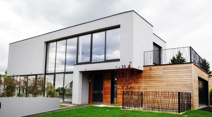
The key purposes of the external cladding of the façade walls are to boost resistance to weather and achieve the desired outer appearance. Care is recommended in the choice of the external cladding material to consider not only its weather-resistance features, but also its reaction to fire, and in determining the proportion of unprotected areas (openings and presence of combustible materials). There is an enormous diversity of façade cladding materials and types that can be applied on-site, such as the External Thermal Insulation Composite System (ETICS) (Figure 9) and ceramic tiles, even shutters and panels that are prefabricated and made of glass, metal and other variations of composite materials.
Figure 9: Timber frame house with ETICS external cladding (Rusticasa, 2022)
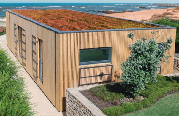
Wood cladding has a variety of patterns and textures (Figure 10), making the house aesthetically pleasing, with boards of different widths and profiles which can be arranged vertically, horizontally or diagonally with juxtaposed or open joints, in addition to being ideal for buildings whose elementary construction material is timber.


The installation of mechanical, electrical and water services in the timber structure construction can be done by applying cables, pipes and conduits on-site, provided that the structure is already protected against the weather, or while still at the factory, thus reducing the on-site activities. These systems can be incorporated in the wall members and floor of the timber construction between the spaces formed by the structure or supported over the internal cladding and coatings.
The modular concepts and degree of prefabrication can vary in the case of a timber frame system. In terms of geometry, the components can be classified as flat or volumetric (3D) (Figure 11).
Figure 11: Types of modularity for timber frame houses. (a) Flat; (b) Volumetric (TRADA, 2008) (a) Planos; (b) Volumétricos (TRADA, 2008)
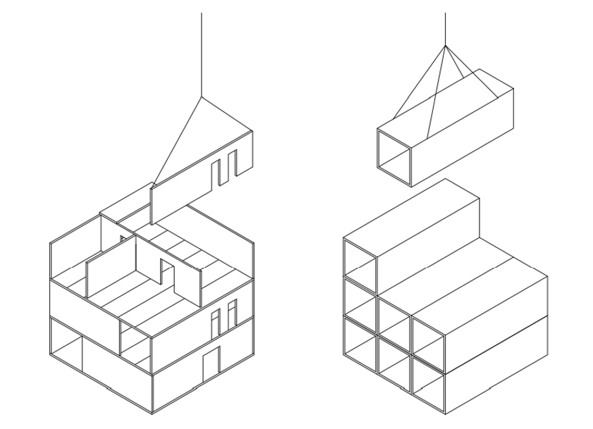
The flat components, forming walls, flooring or roofing, are usually personalised to meet their specifications and requirements, and can be prepared at varied levels of prefabrication: they can arrive on-site already with functional and finishing layers; with cuts and openings made for passing pipes and cables, or even with the infrastructures already installed; with interlocks for joining members and structural connectors; with doors and windows; among others.
Finally, the volumetric components correspond to the 3D units, this means large semi-independent structural units composed of linear or flat members indicated above which can form individual houses or a series of houses. In this case, the degree of prefabrication varies according to the complexity of the assembly system, from a rough structure to a fully watertight one, equipped with infrastructures and furniture. This is effective and suitable for repetitive housing units, being economically viable merely as a result of this condition.
The transport of the components can be one of the key requirements to bear in mind in their design and systematisation, being greatly restricted by the permissible dimensions imposed by the containers or dimensions of the roads. In all truth, the work that can be optimised in the construction yard is almost inversely proportional to the planning and project needs involved.